Address
Blyth, Northumberland
U.K. NE24 2QW
Telephone
+44(0)1670 336766
Opening Hours
Monday to Friday: 08:00 - 17:30
Current carrying capacity tables for automotive cable across PVC 80°C, PVC 105°C, XLPE/XLPO and PTFE/Silicone insulation types — three ambient temperatures, resistance data for volt drop calculation, and a plain-English guide to why insulation type and routing both matter. Free reference document from Voltforge.
Automotive cable current rating reference — current carrying capacity tables for stranded copper flex cable in sub-60V DC automotive, marine and leisure vehicle applications
This automotive cable current rating guide is a practical rough-and-ready reference for current carrying capacity (ampacity) of stranded copper flex cable in sub-60V DC automotive and marine applications. Figures are derived from averages across SAE J1127 and J1128 data and are suitable for general guidance. They are not a substitute for a full cable sizing calculation on a specific installation.
All figures are for a single conductor in free air at the stated ambient temperature. Real installations are rarely this simple — see the bundling and routing section below.
A cable’s current rating is fundamentally a thermal limit. Current flowing through resistance generates heat. As long as the cable can shed that heat fast enough to keep the conductor and insulation below their rated maximum temperature, it is operating safely. Exceed that temperature and insulation degrades, softens, or fails.
Two temperatures matter: the ambient temperature around the cable, and the maximum rated temperature of the insulation. The higher the ambient, the less headroom the cable has before it reaches its thermal limit — which is why the same cable has a lower current rating in a hot engine bay than in open air at 25°C.
The most common and lowest-cost automotive insulation. Fine for body electrical, interior lighting, and general accessories. Not suitable for under-bonnet runs near heat sources. Adequate flexibility in normal temperatures but stiffens in cold. Poor UV resistance over time. Maximum conductor temperature 80°C. Most budget and mid-range cable falls here. SAE J1128 Type GPT.
Better grade PVC compound with higher temperature rating. Noticeably more flexible than standard PVC and significantly better under-bonnet performance. Still cost-effective. The sweet spot for most quality automotive installations. Common in OEM harnesses from reputable manufacturers. SAE J1128 Type HDT / SXL / GXL.
XLPE (crosslinked polyethylene) and XLPO (crosslinked polyolefin) are related but distinct materials frequently used interchangeably in the trade, which causes confusion. Both use a crosslinking process that creates molecular bonds across the polymer chains, giving better temperature resistance and chemical resistance than standard PVC. XLPO uses a polyolefin base compound rather than pure polyethylene — in practice this gives better low-temperature flexibility, slightly better UV resistance, and is the preferred base compound for most LSZH (low smoke zero halogen) formulations.
When you see LSZH cable, the insulation compound underneath is typically XLPO. HFFR (halogen-free flame retardant) and LSZH describe fire performance characteristics rather than the base compound — they are often the same product. Crosslinked types are available in two main temperature grades: 90°C (standard XLPE/XLPO/FLRY-B) and 125°C (SAE J1128 SXL, GXL, TXL — all crosslinked polyethylene).
A common source of confusion: SXL, GXL and TXL are frequently described as 105°C types in trade literature but the correct SAE J1128 rating is 125°C. Both grades are shown side by side in the ampacity table for this family. European designations: ISO 6722 FLRY-B (90°C, thin-walled), ISO 6722 Class E (125°C), DIN 72551.
The premium end. PTFE (polytetrafluoroethylene) offers outstanding chemical resistance, minimal friction, and conductor ratings to 150°C+. Silicone insulation is exceptionally flexible even at very low temperatures and handles up to 180°C. Both are significantly more expensive and PTFE in particular is less abrasion-resistant than it looks — the insulation is tough chemically but can be cut or abraded more easily than PVC. Used in motorsport, aerospace-adjacent applications, and runs very close to heat sources. SAE J1127 Type SGT (silicone), specialist PTFE not covered by a single SAE type.
The ampacity figures in this document are for a single conductor in free air. The moment you bundle cables together, run them through conduit, or route them behind insulation panels, you reduce their ability to shed heat. Cables in a bundle share heat with each other. The more cables in the bundle, and the more tightly they are packed, the greater the derating required.
A full derating calculation is beyond the scope of this guide. The pragmatic rule is this:
If in doubt, go up a size. Bigger is always better. A cable that runs slightly cool costs almost nothing extra and lasts significantly longer. A cable that runs hot is a fire waiting for a bad day.
Specific situations where you should go up at least one size as a minimum: cables in conduit or trunking, runs behind thermal or acoustic insulation panels, bundles of more than 3–4 cables, any run in an engine bay where ambient regularly exceeds 40°C, and any circuit where the cable run exceeds 3–4 metres (volt drop becomes a factor too).
The primary references for this document are SAE J1127 (battery cables and welding cable) and SAE J1128 (low voltage primary cable), published by SAE International. It is worth explaining why we lead with American standards in a document produced by a British engineering business — because the answer says something useful about the state of the wider standards landscape.
SAE J1127 and J1128 are simply the most comprehensive and practically useful standards available for automotive cable construction and insulation classification. They are prescriptive about conductor construction, insulation compounds, temperature ratings, and dimensional tolerances in a way that the European equivalents are not. When you need to know what a cable actually is and what it will reliably do, SAE did the heavy lifting — and the global automotive industry, including European manufacturers, knows it. You will find SAE type references in German, French, and Italian OEM documentation without apology.
The European picture is more complicated, and it is worth being honest about why. ISO 6722 and DIN 72551 are solid references and widely used in European OEM harnesses. The FLRY-B designation in particular is the dominant European type designation you will encounter on cable datasheets, and we reference it throughout. But the broader European standards landscape for low-voltage automotive electrical systems is fragmented in a way that does not serve the people actually doing the work. ISO 6722 does one thing, DIN 72551 does something slightly different, and the gaps between them are wide enough to drive a poorly specified harness through without technically violating either. Where the OEM standards have been genuinely inadequate, the major vehicle manufacturers have filled the void with internal standards — VW Group’s LV 112 and LV 216 being the most prominent examples — which have become de facto industry references precisely because the official standards left too much unsaid.
BS EN standards in the leisure vehicle sector have their own version of this problem. BS EN 1648, the governing standard for leisure vehicle electrics in the UK, was substantially authored by the major British leisure vehicle OEMs. That is not unusual — standards are routinely developed with industry input — but it does mean the standard reflects the architecture and commercial interests of factory-built leisure vehicles rather than the much wider range of conversions, self-builds, and off-highway applications that make up a significant part of the real-world market. The current edition of both parts dates from 2018 and has not been updated since. More fundamentally, BS EN 1648 is published in two parts which, on close reading, contain provisions that directly contradict each other — a situation that leaves practitioners in the invidious position of having to decide which part of the same standard to follow. If you have ever tried to navigate European cable standards and come away more confused than when you started, that confusion is not a reflection of your ability. The standards are genuinely inconsistent, and the people who work with them professionally know it.
Neither SAE J1127 nor J1128 is freely published. Both are available through SAE International and are not especially difficult to locate with a search engine and a few minutes of patience. ISO 6722 is available through BSI and ISO; DIN 72551 through DIN/Beuth. If you are in the UK and would prefer not to pay for access, British Standards are available free of charge through the British Library’s Business & IP Centre network, based in public libraries across the UK. Individual users can read standards on site at no cost. If you are accessing as a registered business, in our experience the BIPC will email standards to you directly. A search for “Business and IP Centre” plus your nearest city will find your local access point.
SAE J1128 Type GPT · ISO 6722 Class B / DIN 72551 FLY · Max conductor temp 80°C · General body electrical, interior, accessories · Not recommended for under-bonnet heat exposure
| Cable Size | AWG Equiv. | Resistance mV/A/m (= mΩ/m) | 25°C ambient | 40°C ambient | 60°C ambient | Typical Use (free air) |
|---|---|---|---|---|---|---|
| 0.5 mm² | 20 AWG | 36.0 | 8 A | 7 A | 5 A | Sensor/signal wiring |
| 0.75 mm² | 18 AWG | 24.5 | 10 A | 9 A | 7 A | Lighting, low current accessories |
| 1.0 mm² | 17 AWG | 18.1 | 13 A | 11 A | 9 A | Lighting, instruments |
| 1.5 mm² | 15 AWG | 12.1 | 17 A | 15 A | 12 A | Lighting circuits, horns |
| 2.5 mm² | 13 AWG | 7.4 | 24 A | 21 A | 17 A | Main lighting, small motors |
| 4.0 mm² | 11 AWG | 4.6 | 32 A | 28 A | 22 A | Starter circuits (small), fans |
| 6.0 mm² | 10 AWG | 3.1 | 41 A | 36 A | 28 A | Alternator feeds, heavy accessories |
| 10.0 mm² | 8 AWG | 1.8 | 57 A | 50 A | 39 A | Main feed cables, winches |
| 16.0 mm² | 6 AWG | 1.1 | 76 A | 66 A | 52 A | Main feed, high-current accessories |
| 25.0 mm² | 4 AWG | 0.727 | 101 A | 88 A | 69 A | Battery-to-distribution feed |
| 35.0 mm² | 2 AWG | 0.524 | 125 A | 109 A | 85 A | Battery cables, main feeds |
| 50.0 mm² | 1/0 AWG | 0.387 | 151 A | 131 A | 103 A | Battery/starter cables |
| 70.0 mm² | 2/0 AWG | 0.268 | 192 A | 167 A | 131 A | Heavy battery/starter cables |
| 95.0 mm² | 3/0 AWG | 0.193 | 232 A | 202 A | 158 A | Very heavy duty, starter motors |
| 120.0 mm² | 4/0 AWG | 0.153 | 274 A | 238 A | 187 A | High current inverter/starter feeds |
| 150.0 mm² | 300kcmil | 0.124 | 305 A | 265 A | 208 A | Maximum automotive runs |
| 185.0 mm² | 350kcmil | 0.099 | 340 A | 296 A | 232 A | Specialist high-current only |
| 240.0 mm² | 500kcmil | 0.0762 | 400 A | 348 A | 273 A | Specialist high-current only |
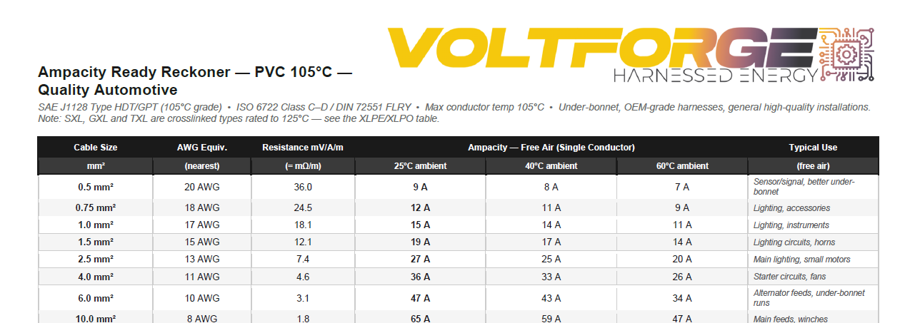
SAE J1128 Type HDT/GPT (105°C grade) · ISO 6722 Class C–D / DIN 72551 FLRY · Max conductor temp 105°C · Under-bonnet, OEM-grade harnesses, general high-quality installations. Note: SXL, GXL and TXL are crosslinked types rated to 125°C — see the XLPE/XLPO table.
| Cable Size | AWG Equiv. | Resistance mV/A/m (= mΩ/m) | 25°C ambient | 40°C ambient | 60°C ambient | Typical Use (free air) |
|---|---|---|---|---|---|---|
| 0.5 mm² | 20 AWG | 36.0 | 9 A | 8 A | 7 A | Sensor/signal, better under-bonnet |
| 0.75 mm² | 18 AWG | 24.5 | 12 A | 11 A | 9 A | Lighting, accessories |
| 1.0 mm² | 17 AWG | 18.1 | 15 A | 14 A | 11 A | Lighting, instruments |
| 1.5 mm² | 15 AWG | 12.1 | 19 A | 17 A | 14 A | Lighting circuits, horns |
| 2.5 mm² | 13 AWG | 7.4 | 27 A | 25 A | 20 A | Main lighting, small motors |
| 4.0 mm² | 11 AWG | 4.6 | 36 A | 33 A | 26 A | Starter circuits, fans |
| 6.0 mm² | 10 AWG | 3.1 | 47 A | 43 A | 34 A | Alternator feeds, under-bonnet runs |
| 10.0 mm² | 8 AWG | 1.8 | 65 A | 59 A | 47 A | Main feeds, winches |
| 16.0 mm² | 6 AWG | 1.1 | 87 A | 79 A | 63 A | Main feed, high-current accessories |
| 25.0 mm² | 4 AWG | 0.727 | 115 A | 105 A | 84 A | Battery-to-distribution feed |
| 35.0 mm² | 2 AWG | 0.524 | 143 A | 130 A | 104 A | Battery cables, main feeds |
| 50.0 mm² | 1/0 AWG | 0.387 | 173 A | 157 A | 126 A | Battery/starter cables |
| 70.0 mm² | 2/0 AWG | 0.268 | 220 A | 200 A | 160 A | Heavy battery/starter cables |
| 95.0 mm² | 3/0 AWG | 0.193 | 266 A | 242 A | 194 A | Very heavy duty |
| 120.0 mm² | 4/0 AWG | 0.153 | 314 A | 286 A | 229 A | High current inverter/starter feeds |
| 150.0 mm² | 300kcmil | 0.124 | 350 A | 319 A | 255 A | Maximum automotive runs |
| 185.0 mm² | 350kcmil | 0.099 | 390 A | 355 A | 284 A | Specialist high-current only |
| 240.0 mm² | 500kcmil | 0.0762 | 460 A | 419 A | 335 A | Specialist high-current only |
SAE J1128 SXL/GXL/TXL (125°C) · ISO 6722 FLRY-B / Class E · DIN 72551 · LSZH/HFFR compounds typically XLPO-based · 90°C and 125°C grades compared side by side
Note: SXL, GXL and TXL (SAE J1128) are crosslinked polyethylene rated to 125°C. FLRY-B and standard XLPO/LSZH compounds are typically rated to 90°C. ★ column = typical use key below.
| Cable Size | AWG Equiv. | Res. mV/A/m | XLPE/XLPO 90°C — ISO 6722 FLRY-B / DIN 72551 / SAE HDT | XLPE/XLPO 125°C — SAE J1128 SXL/GXL/TXL / ISO 6722 Class E | ★ | ||||
|---|---|---|---|---|---|---|---|---|---|
| 25°C | 40°C | 60°C | 25°C | 40°C | 60°C | use | |||
| 0.5 mm² | 20 AWG | 36.0 | 9 A | 8 A | 6 A | 10 A | 9 A | 9 A | 1 |
| 0.75 mm² | 18 AWG | 24.5 | 11 A | 10 A | 8 A | 13 A | 12 A | 11 A | 2 |
| 1.0 mm² | 17 AWG | 18.1 | 14 A | 12 A | 10 A | 16 A | 15 A | 14 A | 3 |
| 1.5 mm² | 15 AWG | 12.1 | 18 A | 16 A | 13 A | 21 A | 20 A | 18 A | 4 |
| 2.5 mm² | 13 AWG | 7.4 | 26 A | 23 A | 18 A | 30 A | 28 A | 26 A | 5 |
| 4.0 mm² | 11 AWG | 4.6 | 35 A | 30 A | 25 A | 40 A | 37 A | 34 A | 6 |
| 6.0 mm² | 10 AWG | 3.1 | 45 A | 39 A | 32 A | 52 A | 48 A | 45 A | 7 |
| 10.0 mm² | 8 AWG | 1.8 | 62 A | 54 A | 43 A | 72 A | 67 A | 62 A | 8 |
| 16.0 mm² | 6 AWG | 1.1 | 83 A | 72 A | 57 A | 96 A | 89 A | 83 A | 9 |
| 25.0 mm² | 4 AWG | 0.727 | 110 A | 96 A | 76 A | 127 A | 118 A | 109 A | 10 |
| 35.0 mm² | 2 AWG | 0.524 | 137 A | 119 A | 94 A | 158 A | 147 A | 136 A | 11 |
| 50.0 mm² | 1/0 AWG | 0.387 | 165 A | 144 A | 113 A | 191 A | 178 A | 164 A | 12 |
| 70.0 mm² | 2/0 AWG | 0.268 | 210 A | 183 A | 144 A | 243 A | 226 A | 209 A | 13 |
| 95.0 mm² | 3/0 AWG | 0.193 | 253 A | 220 A | 173 A | 294 A | 274 A | 253 A | 14 |
| 120.0 mm² | 4/0 AWG | 0.153 | 299 A | 260 A | 205 A | 347 A | 323 A | 298 A | 15 |
| 150.0 mm² | 300kcmil | 0.124 | 334 A | 291 A | 229 A | 387 A | 360 A | 333 A | 16 |
| 185.0 mm² | 350kcmil | 0.099 | 372 A | 324 A | 255 A | 431 A | 401 A | 370 A | 17 |
| 240.0 mm² | 500kcmil | 0.0762 | 437 A | 380 A | 299 A | 507 A | 472 A | 436 A | 18 |
★ Typical use key: 1 Signal/sensor, fire-safe | 2 Lighting, accessories | 3 Lighting, instruments | 4 Lighting circuits | 5 Main lighting, motors | 6 Fans, motor feeds | 7 Alternator, under-bonnet | 8 Main feeds, winches | 9 High-current accessories | 10 Battery feeds | 11 Battery cables | 12 Battery/starter | 13 Heavy battery/starter | 14 Very heavy duty | 15 Inverter/starter feeds | 16 Maximum runs | 17 Specialist high-current | 18 Specialist high-current
SAE J1127 Type SGT (silicone) / specialist PTFE · No direct European standard equivalent · Max conductor temp 150°C+ (PTFE) / 180°C (silicone) · Motorsport, aerospace-adjacent, extreme heat proximity
| Cable Size | AWG Equiv. | Resistance mV/A/m (= mΩ/m) | 25°C ambient | 40°C ambient | 60°C ambient | Typical Use (free air) |
|---|---|---|---|---|---|---|
| 0.5 mm² | 20 AWG | 36.0 | 10 A | 10 A | 9 A | Motorsport, aerospace-grade signal |
| 0.75 mm² | 18 AWG | 24.5 | 13 A | 12 A | 12 A | High-temp environments |
| 1.0 mm² | 17 AWG | 18.1 | 16 A | 15 A | 15 A | Instruments, high-temp runs |
| 1.5 mm² | 15 AWG | 12.1 | 21 A | 20 A | 19 A | High-temp lighting/accessories |
| 2.5 mm² | 13 AWG | 7.4 | 30 A | 29 A | 27 A | High performance accessories |
| 4.0 mm² | 11 AWG | 4.6 | 40 A | 38 A | 36 A | Motorsport feeds |
| 6.0 mm² | 10 AWG | 3.1 | 52 A | 50 A | 47 A | Engine bay, high-temp runs |
| 10.0 mm² | 8 AWG | 1.8 | 72 A | 69 A | 65 A | Main feeds, high-temp |
| 16.0 mm² | 6 AWG | 1.1 | 96 A | 92 A | 87 A | High-current, high-temp |
| 25.0 mm² | 4 AWG | 0.727 | 127 A | 122 A | 115 A | Battery feeds, engine proximity |
| 35.0 mm² | 2 AWG | 0.524 | 158 A | 152 A | 144 A | Battery cables, extreme environments |
| 50.0 mm² | 1/0 AWG | 0.387 | 191 A | 183 A | 174 A | Heavy battery/starter |
| 70.0 mm² | 2/0 AWG | 0.268 | 243 A | 233 A | 221 A | Heavy duty, high-temp |
| 95.0 mm² | 3/0 AWG | 0.193 | 294 A | 282 A | 267 A | Very heavy, extreme environments |
| 120.0 mm² | 4/0 AWG | 0.153 | 347 A | 333 A | 316 A | Maximum, motorsport/specialist |
| 150.0 mm² | 300kcmil | 0.124 | 387 A | 372 A | 352 A | Specialist only |
| 185.0 mm² | 350kcmil | 0.099 | 431 A | 414 A | 392 A | Specialist only |
| 240.0 mm² | 500kcmil | 0.0762 | 507 A | 487 A | 461 A | Specialist only |
⚠ All figures are for a single conductor in free air at the stated ambient temperature. Real installations are rarely this simple. Derate for bundled, conduit, or concealed runs — when in doubt, go up a size. A cable that runs cool costs almost nothing extra and lasts significantly longer. Ampacity is a thermal limit; always check volt drop separately (mV/A/m × A × m ÷ 1000 = volt drop in volts). Figures derived from averages across SAE J1127 and J1128 data — suitable for general guidance only. Consult the cable manufacturer datasheet for precise figures for a specific product. These figures are not a substitute for a full cable sizing calculation on a specific installation.
This document is provided for general reference and educational purposes only. The figures and guidance contained in it are derived from published industry standards and are intended to support informed decision-making — they are not a substitute for a full engineering assessment of a specific installation. It is the responsibility of the installer to carry out an appropriate assessment for their specific application and to ensure that any installation complies with applicable standards, regulations, and any vehicle or equipment manufacturer requirements. Voltforge and Zeromachine Ltd accept no liability for loss, damage, injury or consequential loss arising from the use of or reliance on the information in this document. If you are in any doubt about the suitability of a cable size or installation method for your application, stop and get proper advice before proceeding.
The assemblies in our shop use Class 5 fine-stranded automotive flex and OEM-spec components throughout — because the cable spec matters as much as the connector. Browse the Deutsch DT pigtail range →