Address
Blyth, Northumberland
U.K. NE24 2QW
Telephone
+44(0)1670 336766
Opening Hours
Monday to Friday: 08:00 - 17:30

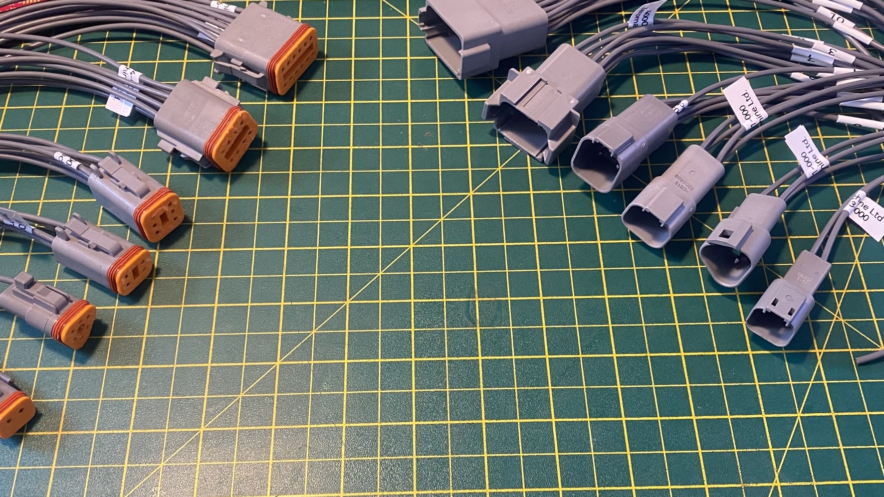
Ask an electrical engineer why they don't say male and female connectors and brace yourself for a proper answer. It's not politics. It's precision — and once you understand why, you'll never specify a connector the same way again.
Not sure of a term? Jump to the glossary →
Let’s get this out of the way immediately.
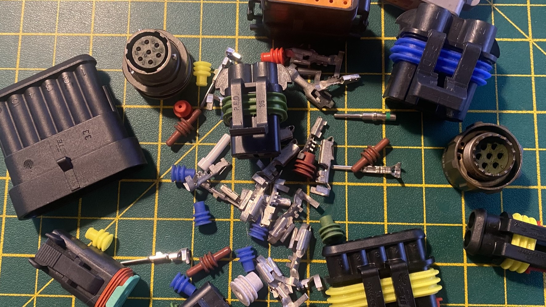
When an electrical engineer winces slightly at “male connector” or “female connector,” they’re not having a moment. They haven’t just come back from a sensitivity workshop. They’re not quietly judging your vocabulary choices.
They’re reacting to imprecision. Because in a discipline where imprecision costs time, money, or worse — “male” and “female” applied to a multipole connector housing are not just vague. They’re technically wrong. And once you see why, you can’t unsee it.
The multipole electrical connector — a single housing carrying more than one circuit, mating in a single action — is largely a product of the Second World War.
Before the war, most electrical connections were made one wire at a time: screw terminals, soldered joints, individual bullet connectors. As aircraft became more complex and electronics proliferated in military equipment, that approach stopped scaling. You needed to connect dozens of circuits reliably, repeatedly, under vibration, at altitude, in the dark, by people who weren’t electricians. The circular multipin connector — the kind still recognisable today in the Cannon and Amphenol families — was the answer. Locking, keyed, sealed against the environment, connectable without looking.
After the war, that technology filtered into industrial and automotive applications. By the 1960s and 70s, as electronics spread through vehicles and machinery, the automotive connector industry industrialised rapidly. Molex, AMP (now TE Connectivity), Delphi (now Aptiv), and eventually Deutsch developed the rectangular multipole connector families that dominate vehicle wiring today — designed for volume assembly, field serviceability, and the specific brutality of the automotive environment: vibration, temperature cycling, moisture, and the occasional pressure wash.
The terminology that came with them — plug, receptacle, pin contact, socket contact — was inherited from the aerospace world that spawned them. Precise, unambiguous, and deliberately decoupled from any physical metaphor that might cause confusion at scale.
Which brings us to the problem.
Here’s the insight that changes everything — and this is specifically about multipole connector housings. We’re not talking about insulated spade terminals, bullet connectors, or ring terminals here. Those are single-pole contacts, they are genuinely gendered at the contact level, and “male spade / female spade” is perfectly correct and unambiguous. That’s a different post.
What we’re talking about are the multipole housing families — Deutsch DT, Aptiv GT, Amphenol AT, Molex MX, and their siblings. And for these, the male/female framing breaks down the moment you look at it honestly.
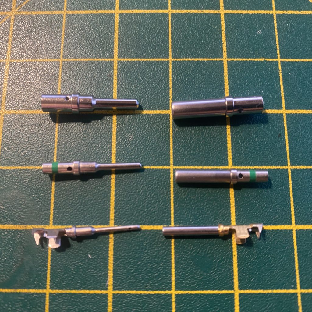
The pin protrudes. The socket receives. That’s where the geometric metaphor — if we’re using it at all — actually applies. At the contact. The tiny crimped terminal inside the housing.
The shell? The body? The big plastic thing you’re holding? That’s neutral. It has a mating geometry, certainly — one half inserts into the other — but the contact inside it might be a pin, or it might be a socket, and the two are completely independent of which shell body you’re looking at.
This is not a theoretical edge case. On a Deutsch DT series connector, the plug — the half on the flying lead, the one that inserts — is designated DT06. The 06 shell is the insertable half. And it takes socket contacts. The geometry that most people would instinctively call “male” contains what the standard correctly calls “female” contacts.
So when someone asks “do I need the male or the female?” — which half are they describing? The shell geometry? The contact type? Are they the same on this connector, or opposite? Now you need a conversation to find out. That conversation is the problem. “Socket contact in a plug shell” has no ambiguity whatsoever.
Picture a workshop. Someone’s building a lighting loom — nothing exotic, a straightforward six-circuit connector. They’ve ordered their parts. They’re confident. They’ve got “the male one.”
They hand it over. Shell’s right. Mating geometry checks out. They start loading contacts.
Wrong contacts. They’ve got pins where they need sockets, because the shell they correctly identified as the insertable half — the one most people would call “male” — takes socket contacts on this particular connector. The two concepts point in opposite directions, and nobody flagged it because the language they used didn’t require them to think about contacts and shells separately.
Half an hour, a parts re-order, and a slightly bruised confidence later, the job’s back on track.
This happens. Regularly. Not because people are careless — because the terminology they learned actively obscures the thing they need to know.
If you want a single product that demolishes “male and female” as a useful descriptor, it’s the TE Connectivity Amp MateNLok.
The MateNLok has two housing genders — there’s a plug half and a receptacle half, and they mate in one orientation. Standard so far. Here’s where it gets interesting: both housings accept both pin contacts and socket contacts. You can load pins into the plug. You can load sockets into the plug. Same goes for the receptacle. The housing geometry and the contact type are entirely independent, by design.
This isn’t a bug. It’s not a manufacturing oversight. It’s a deliberate feature that gives the assembler flexibility in how circuits are allocated. And it means that “male MateNLok” is not just imprecise — it’s meaningless. You’ve described the shell and told the person nothing about what’s carrying the current.
TE Connectivity are not a small operation. The MateNLok has been in continuous production for decades and is used in millions of vehicles. When one of the world’s largest connector manufacturers builds a product that structurally cannot be described by male and female terminology, that’s not an edge case. That’s the industry telling you something.
Deutsch — now under TE Connectivity — specifies plugs and receptacles, pin contacts and socket contacts throughout their documentation. The DT, DTM, and DTP series datasheets don’t use male and female anywhere. Not once.
Aptiv (formerly Delphi), whose GT 150 series is ubiquitous in automotive applications, uses identical language. Plug. Receptacle. Pin. Socket contact. Their engineers didn’t sit down and make a style choice — they adopted the terminology that removes ambiguity from a multi-billion-unit connector range.
Amphenol, spanning aerospace, military, industrial and automotive — same story. Their AT series documentation is consistent throughout: contacts are pins or sockets, housings are plugs or receptacles.
The fact that every major connector manufacturer independently arrived at the same language isn’t a coincidence. It’s the industry converging on the terminology that actually works.
A plug can carry pin contacts or socket contacts. A receptacle can carry pin contacts or socket contacts. All four combinations exist in real products from real manufacturers — and that’s before you get into the tab, blade, and sleeve contact naming conventions that Aptiv, TE, and others use in their own ranges.
That’s precisely why “male” and “female” applied to a housing are useless — there’s no reliable relationship between the housing geometry and the contact type inside it. It doesn’t simplify anything. It just moves the ambiguity around.
The correct approach is straightforward: describe the housing and the contact separately, every time. Plug or receptacle for the housing. Pin, socket, tab, blade, or sleeve for the contact — whatever the manufacturer calls it in the datasheet. If you’re not sure, look it up. The datasheet is always right. “The male one” is only ever right by accident.
The Deutsch DT range illustrates this perfectly. Their convention — consistently applied across the DT, DTM and DTP families — puts socket contacts in the plug and pin contacts in the receptacle. The housing that inserts carries the receiving contact. The housing that receives carries the inserting contact. Exactly the opposite of what the gender shorthand would lead you to expect. And once you know that, “male Deutsch connector” becomes not just vague but actively misleading.
And once you’re thinking in those terms, a piece of practical convention starts to make sense that would otherwise seem arbitrary: traditionally, the hot side — the live feed — travels with the socket contact. Not the pin.
The reason is straightforward. A socket contact is recessed inside the housing cavity. A pin contact protrudes. During mating and unmating — particularly on a partially mated connector, or one being handled carelessly — an exposed live pin is a short circuit or a shock waiting to happen. The socket shields the live conductor behind a wall of plastic. It won’t save you from determined incompetence, but it dramatically reduces the risk of an accidental bridge across a live contact during a connector swap.
It’s a convention, not a universal law — there are applications where it’s reversed for perfectly good reasons — but it’s the convention the industry converged on, and understanding why it exists means you apply it with judgment rather than just copying what the last person did.
One final note. Distributor websites, influencer build videos, and forum posts are full of confident people using the wrong terminology — and some of it has been wrong long enough that it looks authoritative. If you’re unsure about any connector specification, go to the source. The OEM datasheet. The manufacturer’s product page. That’s where the correct terminology lives, that’s where the specifications are guaranteed, and that’s where you find out what you actually need before you order the wrong thing.
It’s worth saying that not every distributor gets this wrong — some take specification and terminology seriously and it shows in how they describe and list their products. They’re worth finding and worth supporting. But even the good ones are interpreting the OEM documentation, not replacing it. When it matters, go to the source.
Alternatively — that’s exactly the work we do at Voltforge. Every product we list is specified from OEM documentation, described in the correct terms, and supplied as genuine product. If the datasheet says socket contact in a plug shell, that’s what we’ll tell you, that’s what we’ll sell you, and that’s what’ll turn up. And if you’re not sure, just ask — we’re always happy to talk it through. That’s what we’re here for.
None of this means the workshop banter needs to change. When it’s just the two of you and you’re both looking at the same bench, “pass me the male one” is probably fine — we’re all guilty of it. Language is contextual.
But the moment it goes on a purchase order, a BOM, a wiring diagram, or a message to a supplier — check, check, and check again. The terminology exists to make that process fool proof, and it genuinely took us years to get our heads around which contact goes in which housing across different manufacturer ranges. Distributors get it wrong. Experienced engineers get it wrong. The only source you can fully trust is the OEM datasheet — and even then, read it twice.
So go to the manufacturer. Read the datasheet. Or just ask us — we’ve done the reading, we’ve made the mistakes, and we stock the right parts. That’s what we’re here for.
Voltforge designs and supplies connector assemblies and wiring solutions for people who want it done right. Browse our range at shop.voltforge.co.uk
<a name=”glossary”></a>
We’re not even going to pretend this is exhaustive — the connector world has more terminology than any single glossary can cover, and every manufacturer seems determined to coin their own. What follows are the terms you’re most likely to encounter in the harsh-environment multipole families we work with day to day — leisure vehicle, van conversion, and off-highway applications. If something’s missing, tell us and we’ll add it. And as always, when it really matters, the OEM datasheet is the authority, not us.
Housing / Shell The outer plastic or composite body of a connector. The housing defines the mating geometry, the circuit count, the keying, and the environmental sealing class. It does not, on its own, tell you anything about the contact type inside it. Housings are specified separately from contacts and assembled during the harness build process.
Plug The connector half that inserts into its counterpart during mating. Typically the half on the flying lead — the one that moves. In vehicle harness conventions, the plug is usually the harness side of the connection. Does not imply anything about the contact type loaded inside it.
Receptacle The connector half that receives the plug. Typically the fixed half — panel mounted, chassis mounted, or attached to a device or module. Also referred to as a socket or header depending on the manufacturer and application. Says nothing about the contact type inside.
Pin contact The contact with the protruding cylindrical geometry — the one that enters the socket contact during mating to complete the circuit. Crimped onto the conductor before insertion into the housing. Pin contacts are sized to specific wire gauge ranges; using the wrong size produces an unreliable crimp and a connector that will fail in service. Always verify the contact part number against your wire gauge.
Socket contact The contact with the receiving geometry — the one the pin enters. Also crimped onto the conductor before housing insertion. On many connector families, socket contacts are spring-loaded to maintain contact force over the life of the connection. The same wire gauge matching rules apply as for pin contacts.
Tab contact / Blade contact The flat, planar equivalent of a pin contact — an inserting contact with a flat profile rather than a cylindrical one. TE Connectivity use “tab” extensively in their documentation; “blade” appears across Aptiv, Molex, and others. Functionally the same principle as a pin contact — it inserts, it carries current, it does not receive. The receiving counterpart is a sleeve contact. Common in automotive body and powertrain connector families.
Sleeve contact The receiving counterpart to a tab or blade contact in families where “socket” isn’t the manufacturer’s preferred term. A sleeve contact wraps around or accepts the tab or blade geometry to complete the circuit. Functionally equivalent to a socket contact — the terminology is manufacturer-specific, not a meaningful technical distinction.
Crimp contact The generic term for any contact — pin, socket, tab, blade, or sleeve — that is terminated to its conductor by crimping rather than soldering. The correct term for almost every contact in a modern multipole connector. Soldering contacts into multipole housings is not recommended and in most automotive and industrial applications is explicitly prohibited: it wicks solder into the wire strands, creates a hard spot, and causes fatigue failures at the point where flexibility is most needed. Crimp it.
Flag contact / Right-angle contact A contact where the crimp barrel sits at 90 degrees to the mating axis. Used where routing wires parallel to a mating face rather than straight back — tight panel installations, behind-dash applications, anywhere axial wire exit would foul adjacent components. Available in pin and socket variants across multiple families.
Wire seal An individual elastomeric seal that fits over the conductor and sits behind the contact in the housing cavity, sealing the wire entry point against moisture ingress. Required in every populated cavity on a sealed connector. Wire seals are sized to a specific wire diameter range — fitting the wrong seal, or omitting it, removes the IP rating of the connector at that cavity. Not optional.
Seal plug / Cavity plug A solid elastomeric plug used to seal any unpopulated cavity in a sealed connector housing. If you’ve got a six-way housing with four circuits, the remaining two cavities must be plugged. Without them, you do not have a sealed connector. You have a funnel. Inexpensive, frequently forgotten, always important.
Wedge lock A secondary retention component used in Deutsch and similar connector families. Once contacts are inserted into the housing, the wedge lock is pressed in from the mating face, mechanically locking each contact against pull-out forces. Colour coded by contact series — they are not interchangeable between series even where they appear physically similar. Always confirm the wedge lock part number against the housing and contact family being used.
Terminal position assurance (TPA) A secondary locking component that engages after contact insertion to confirm and lock the contacts in their fully seated position. Where a wedge lock prevents pull-out, a TPA also provides positive confirmation that each contact has reached its correct seated depth. Found on connectors where full contact engagement is safety-critical and visual inspection alone is insufficient.
Connector position assurance (CPA) A clip or slide that bridges across the fully mated connector pair — both plug and receptacle together — to confirm full mating and prevent inadvertent unmating due to vibration, snagging, or handling. Distinct from TPA, which operates at the contact level within a single housing half. In high-vibration environments, fit the CPA. It exists for a reason.
Locking ramp / Secondary lock The integral or separate feature that retains the mated connector halves together and resists unmating forces. In many connectors this is a primary integral latch built into the housing. A secondary lock — whether a CPA clip, a sliding lock bar, or an over-centre latch — provides a second line of defence. In vehicle applications subject to vibration, thermal cycling, or accidental handling, primary latch alone is often insufficient for critical circuits.
Ferrule A metal sleeve crimped over the stripped end of a stranded wire to consolidate the strands before insertion into a screw terminal or push-in terminal block. Common in DIN rail panel wiring. Not used in crimp contact connector assemblies — but frequently confused with contact crimping by those new to the discipline.
IDC contact (Insulation Displacement Contact) A contact that cuts through the wire insulation on insertion, making the electrical connection without stripping. Common in low-current signal applications — ribbon cable, some data connectors. Not used in the sealed multipole connector families covered in this series, but worth knowing exists so you don’t accidentally specify it somewhere it doesn’t belong.
Think we’ve missed a term? Get in touch — this glossary will grow.
All manufacturer and product names referenced in this article — including Deutsch, TE Connectivity, Amp, MateNLok, Aptiv, Molex, and Amphenol — are the trademarks or registered trademarks of their respective owners. Their use here is for identification and editorial reference purposes only. Zeromachine Ltd and Voltforge are not sponsored by, affiliated with, or in any formal promotional relationship with any manufacturer named in this article — we purchase their products through distribution because we believe they are the right choice for the applications we serve. Every manufacturer referenced here has earned their place in our toolkit, and every one of them has strengths and weaknesses. The right connector for the job isn’t always the same connector — and part of what we do is help you choose the right one for your application rather than just defaulting to a familiar name. All product specifications should be verified against current OEM documentation before use.
